NadeoImporter [update 2019/10/09]

Discuss everything related to custom data creation.

Moderator: NADEO

User avatar
string
Posts: 44
Joined: 10 Mar 2011, 10:48
Location: Norway

Re: Custom Objects Specifications

Post by string »

For those who prefer to model in Lightwave (only deals with stadium env):

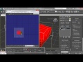
In Lightwave the measurements for a "block" in Stadium is 32m x 32m x 8m (same as the regular square circuit block). This will turn up in 3dsmax as the right size if you export to .3DS from LW with all export options unchecked (rotate, scale etc). And remember to rotate it forward 90 degrees around origin and triple it first (when looking at it in the "right" viewport, rotate towards the left).

Any Lightwave user MUST first import the model (including vehicles) into 3dsmax or blender to set the properties & UVW. Even if you find an FBX export plugin for LW it won't work. Yes it sucks to have to learn another 3d prog just for this, but it isn't really that complicated since you already use another 3d prog. Plus there are tons of good tuts on youtube ;) Also, Justspeeding made a tutorial for using the nadeoimporter, BUT...as the brilliant man he is, he also included how to set up your object in 3dsmax in the same video ( http://www.tm-tube.com/video/27674/tuto ... eoimporter ).

Just as a little sidenote (after you have watched it): you don't have to collapse the modifiers. Personally I made one UVW and then copied and pasted it and just set the new one to mapchannel 2, then name the mapchannels "Material" and "Lightmap" as usual. It seems to work just fine.

Not sure if it's mentioned anywhere, but the size of a standard "block" gridposition in Stadium is 32x32 width and depth (and the height is usually 8).
In the xml, the units(steps) for the aforementioned stadium circuit block would be 32x8x32. So meters in LW = xml value.
If you made a circuit block just like that, the xml could e.g. read:
<Object>
<GridSnap HStep="32" VStep="8" HOffset="16" VOffset="0"/>
</Object>
Where Hstep is horizontal steps. 32 being the whole length of this object, so it can't overlap in the editor and fit together perfectly. Same with VStep: vertical steps, in this case 8 which is the exact height of this object. In this case however, the pivot is right smack in the middle so the object grid doesn't fit with the default grid. if u lined it up with blocks that comes with the game u would get something like _-_-_-_-_- meaning u gotta push it half the object length to make it line up. Which is why the HOffset is set to 16, making it more like ======.

The pivot settings are more hazy to me still, but I know you can change the pivot position for the object. Perhaps that's all they do? I checked the files in the "Dolmen" example, but I got no idea why there are multiple pivot entries in one xml. I also figured out that the middle value of the three is the vertical axis(Z). It's possible I could drop the HOffset and just move the pivot, but it works fine for now. I also still don't know how to make it move upwards without something under to support it. But then again...this is all still beta ;)

Good luck LW people :thumbsup:

PS: Anyone know how to get a dirt piece from stadium? Being a dirt racer I wanna make dirt bits, but since the ground in a dirt-road bit is curved it's impossible to make it fit other dirt bits without having a template first.
User avatar
darmaya
Posts: 203
Joined: 08 Sep 2011, 14:20

Re: Custom Objects Specifications

Post by darmaya »

Hi String,
cool post :thumbsup:

Pivots

Dirty pieces
I'd made a set of "dirty" and "snowy" ramps,
using the displace technique.
First i draw a heightmap of ramp object,
then i displace it over a 128x128 grid (or more),
Image
Image
Image
Image
The problem is how to draw a right "gradient" heightmap:
(do not use this, is a jpg, it is very poor and it is "convex", try instead to build your own)
Image
then i add another modifier that made that "concave"

I do not use the "block-snap" in xml,
but just the second value (yes, it is height from ground)
with 10 cm steps to "embed" the object over the ground or to match the height of a block.

Code: Select all

<Object>
   <Pivots>
      <Pivot Pos="0 0 0"/>
      <Pivot Pos="0 0.1 0"/>
      <Pivot Pos="0 0.2 0"/>
      <Pivot Pos="0 0.3 0"/>
	  <Pivot Pos="0 0.4 0"/>
	  <Pivot Pos="0 0.5 0"/>
	  <Pivot Pos="0 0.6 0"/>
   </Pivots>
</Object>
Image
Image
User avatar
string
Posts: 44
Joined: 10 Mar 2011, 10:48
Location: Norway

Re: Custom Objects Specifications

Post by string »

Thanks darmaya, for that elaborate post :D

Yea, I suppose it can be done like that, but it would still just be a substitute for a "real" dirt section which would fit perfectly with the included defaults.

First of all, the gridsnap example was just that...an example. Some may prefer to leave it smaller to have greater freedom, but ditching it completely seems to me could present a lot of probs when u want 2 objects to fit seamlessly for smooth driving. Plus, we all know how "lovely" the textures look when two objects with same height overlap.

Edit: Checked out a few heightmap tuts on youtube, so I know what it is now, but since I make the block geometry entirely in Lightwave it's not something I'm gonna need. Just gonna use LW subdivision tools to smooth it out before sticking it into max.)

Also...why do u put like 7 different pivot settings into an <object> there? Damien's also had xmls with several pivot lines. I can't see any reason for more than one line with 3 axis values to specify where the pivot goes. Am I missing something?

And last but not least. What material name have you set to the dirt in max? I heard some say it's called StadiumDirt, but I haven't tried yet. Ex. "_TDSN_mycoolname_WTFmaterial"
User avatar
darmaya
Posts: 203
Joined: 08 Sep 2011, 14:20

Re: Custom Objects Specifications

Post by darmaya »

string wrote: Yea, I suppose it can be done like that, but it would still just be a substitute for a "real" dirt section which would fit perfectly with the included defaults.
As i stated before, Nadeo blocks are piece of art, i don't even imagine to build something like that.
string wrote:Edit: Checked out a few heightmap tuts on youtube, so I know what it is now, but since I make the block geometry entirely in Lightwave it's not something I'm gonna need. Just gonna use LW subdivision tools to smooth it out before sticking it into max.)
Oh well, hightmaps are "primitives", but useful to my needs...
string wrote:Also...why do u put like 7 different pivot settings into an <object> there? Damien's also had xmls with several pivot lines. I can't see any reason for more than one line with 3 axis values to specify where the pivot goes. Am I missing something?
To be true, i put 20 pivots for the ramps, and i use just the vertical axis, in order to meke objects fit with blocks...
This method set the "absolute" altitude relative to underlyng terrain or block or object.
I also use in steps of 10 METERS when dealing with MOBject.
string wrote:....What material name have you set to the dirt in max? I heard some say it's called StadiumDirt, but I haven't tried yet. Ex. "_TDSN_mycoolname_WTFmaterial"
The yet misterius naming of game-textures was never explained completely, i don't know why.
I never been able to use it, so i use custom textures.
For what i understand, you must put "BaseMaterial" instead of "Material" for the first UVMap, and the name of the texture "should" be the name of the stadium texture (ProgramData/ManiaPlanet/PacksCache/TMStadiumHD)

I just PM you an example of objects with many pivots...
Image
Fix
Nadeo
Nadeo
Posts: 1256
Joined: 14 Jun 2010, 17:28

Re: Custom Objects Specifications

Post by Fix »

_TDSN_ activates the custom material with custom textures using this special type of shader (Texturecoordinates(UV1)_Diffuse_Specular_Normals). You don't have access to a lot of MaterialModels yet.

If your material name is one of the game's instead of _MaterialModelType_NameofTextures_CollisionType, such as StadiumDirt. then your object will use the game's one.

darmaya : using heightmaps for a single block is ok, i you need a to create a full set of blocks, I fear you'll have to battle with the heightmap precision.
FFD (FreeFormDeformer) are really powerfull old tools.
User avatar
string
Posts: 44
Joined: 10 Mar 2011, 10:48
Location: Norway

Re: Custom Objects Specifications

Post by string »

Well i wasnt looking for a texture, but rather the physical properties of the dirtroad in stadium env. Such as the ones for canyon you've already mentioned, like Stone, Wood, Metal etc.

I was under the impression that one can combine a custom texture, with the physical properties of a material in the game. so that if I for example wanted to make a dirt piece with its own texture, but that used the physical properties of the dirtroad in stadium, the resulting material name would be: _TDSN_Mydirtbits_StadiumDirt .
But from what you're saying, I get the impression that StadiumDirt isn't instead of stone, or wood or rock etc., but rather substitutes the whole material name.

So what it boils down to is: what exactly do I put after _TDSN_Mydirtbits_ to get the physical properties of a stadium dirt road?

Or..if I just use StadiumDirt instead, and it gets the physical properties of a dirtroad. I suppose we will have to align the UVW to the already existing texture. But since we can't access that texture as it's packaged, could u tell if the texture, or rather texture placement, is the same in TM2 as in TMUF?
User avatar
HawkGer
Translator
Translator
Posts: 226
Joined: 16 Jun 2010, 01:11

Re: Custom Objects Specifications

Post by HawkGer »

I guess you can choose from among these physical IDs:
<PhysicalId> = among list {"Concrete", "Grass", "Metal","Dirt", "Rock", "Stone", "Wood", "NotCollidable"}
I would try: "_TDSN_Mydirtbits_Dirt"

Once the Nadeoimporter is updated you can choose among the standard Materiallist and specify "StadiumDirt" for your block which would then use the physical property "Dirt" and one of the standard Nadeo textures (probably StadiumDirt.dds). After that you can modify that texture with a mod if you want...

At least that's how I understand this.
__________________________________________
Btw. I made a video tutorial on object creation with my (hopefully correct) knowledge about this subject:
Object Creation Tutorial

Image

ImageImageImage

Object Creation Tutorial
User avatar
string
Posts: 44
Joined: 10 Mar 2011, 10:48
Location: Norway

Re: Custom Objects Specifications

Post by string »

But of course the "Dirt" option is the physics for the dirt in Canyon and not Stadium, as are all the others too I assume ( except NotCollidable :P ). since stadium wasn't even close to being released when the block creation was implemented. And in addition there are in fact two dirt physicalIDs in Stadium, one for the dirtroad and one for the ground.

So the conclusion then is that one can't make true dirt bits yet, cuz there's 1. No available 3d template of a dirtroad to make it fit seamlessly, and 2. even if the templatemodel was available, The physicalID simply isn't available yet. And 3. even if 1 and 2 was in place, the other dirtbits have connector-ends that change shape when connected, but don't react to the custom objects, at least not yet (only way would be to use a downhill-block to force the connected shape, while still being able to blockmix in the custom road).

Yes it can be made like darmaya did, but thats like asking for dirtbugs (why those still remain in TM2 I don't know. Was every dirt racer's wet dream that something would have been done with those). And it won't be smooth or handle the right way.

Guess the only thing to do then for now is make some approximate objects, and sit back and wait for the materials to be revealed by Nadeo. Maybe make a couple flowerpots...trees...furniture...lol :D
:pop:

Very nice tutorial, Hawk. :thumbsup: :1010

/////////////// Next is a feature suggestion ///////////////

First of all, thanks a million for the rotate object feature on every axis. Just that alone opens up a whole world of possibilities! (Yes every axis. If u're looking for the Z-axis, give + and - a try)
Damien wrote:Note : In the editor, since the Beta2 release, the pivot is chosen automatically according to the surface under the mouse pointer (if you are pointing at ground for instance, it will choose the lowest pivot).
This seems like a bad solution. If there are pivot entries, then use the first of those instead...always (until tab is used), and have ALL other pivot entries available for tabbing...always. Regardless where the pointer is or what the gridsnap says. Full freedom and full control. As it is now it seems to be bouncing all over the place.

Ok, I'll rephrase that: Don't let the computer choose the pivots for us, but give us total control.
An example (with regular 32x8x32 object mentioned above):

<Object>
<GridSnap HStep="32" VStep="8"/> (keep the object under control)
<Pivots>
<Pivot Pos="0 0 0"/> (default placing)
<Pivot Pos="0 0 8"/> (alternative -> 25% horizontal offset)
<Pivot Pos="0 0 16"/> (alternative -> 50% horizontal offset)
<Pivot Pos="0 0 24"/> (alternative -> 75% horizontal offset)

// ...and maybe even a couple more positions for a bit more freedom

<Pivot Pos="0 -4 0"/> (alternative -> 50% vertical offset)
<Pivot Pos="0 -4 8"/> (alternative -> 50% vertical offset and 25% horizontal offset)
<Pivot Pos="0 -4 16"/> (alternative -> 50% vertical offset and 50% horizontal offset)
<Pivot Pos="0 -4 24"/> (alternative -> 50% vertical offset and 75% horizontal offset)

// and a suggestion of my own if it can be done (# could be any character)

<Pivot Pos="# 0 #"/> (alternative -> 0% vertical offset and disables gridsnap horizontal)
<Pivot Pos="0 # 0"/> (alternative -> disables gridsnap vertical and 0% horizontal offset)
<Pivot Pos="# # #"/> (alternative -> disables gridsnap completely)
</Pivots>
</Object>

...which is in a way the same as how it works now (except the #s), but without the annoying automatic pivot selection, and add a hotkey for reset pivot. Also make pivot pos entries relative to HOffset and VOffset if they aren't already. Maybe even add an onscreen msg letting u know which pivot coordinate is currently being used.

This, in addition to mousewheel controlled z axis like with the ingame objects, seems to me like the most sensible and least annoying solution.
Last edited by string on 28 Mar 2013, 16:37, edited 2 times in total.
User avatar
dreadofmondays
Posts: 77
Joined: 12 Jul 2012, 17:21
Location: Australia

Re: Custom Objects Specifications

Post by dreadofmondays »

I've been working on a set of blocks that I'm hoping will be able to be used sort of like a modular city. It'll have different roads that fit together, and buildings and props to create a custom city. :) Here's a test map with some preliminary peices:

Image

It's going fairly well so far, but I'm stuck with lightmapping. Lightmapping both LOD0 and LOD1 to match up is difficult to do and usually introduces errors between the two maps and wasted space; allowing the program to generate lightmaps with correct spacing and projection is a much easier solution, but it generates different maps for both LODs because of the different layout of the polygons. It's making it quite hard to perfect these blocks.

What I really would like is a functionality to use two different lightmap UVs for the different LOD models, if there are two available.
Nadeo, could you please implement this? It would make block creation that much easier! :pil Thanks!
User avatar
darmaya
Posts: 203
Joined: 08 Sep 2011, 14:20

Re: Custom Objects Specifications

Post by darmaya »

@dreadofmonday
curious about the brain behind your citation:

Let me guess:
1. you are brainless and you don't know because of it, instead you suppose to be funny.
2. you like to appear more brainleess of what you are, but the effort is too much for you, 'cause no brain.
3. you are just idiot and want to upgrade to brainless, 'cause you envy alter-fox.
4. you and alter-fox are feathers of a wind, brainless both
5. everything is fine and dandy, and you are a column of our community.

Need translation?
Image
Post Reply

Return to “Title Pack & Custom Data Creation”

Who is online

Users browsing this forum: No registered users and 1 guest