
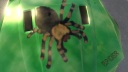
TMarc wrote:The OpenGL TeapotdePaljas wrote:Can someone please give me a hint what I'm doing wrong? It feels like a smoothing group issue:
http://i48.tinypic.com/34htlc6.jpg
I model using 3dsmax, convert to editable mesh, assign smoothing groups (faces in main body are all same group), do the 2 channel unwraps, export to FBX including smoothing groups.
Looks like the UV coordinates are not set properly, if you're talking of a mismatch at the vertical cut.
NadeoImporter [update 2019/10/09]
Moderator: NADEO
Re: Custom Objects Specifications
[Mobo: FOXCONN A7DA-S/A7DA] [CPU: AMD Phenom II X4 940 BE] [Memory: 4GB] [Video: MSI 660 Ti]

Re: Custom Objects Specifications
The diffuse maybe, but what about the normal map?
Re: Custom Objects Specifications
Same story, it's a 256x256 DXT1 DDS with uniform value all over.TMarc wrote:The diffuse maybe, but what about the normal map?
I've uploaded all three maps here.
You must be on the right track though; I just checked the UVW map, and the issues in TM2 are exactly at the seams in 3dsmax. A guess would be that if faces are not connected by UVW coordinates, the importer separates them into different smoothing group, regardless of the model.
But reading the OP I notice I should try TGA maps and let the importer do the translation. I'll give that some tries and let you know. --> EDIT: that doesn't help.
[Mobo: FOXCONN A7DA-S/A7DA] [CPU: AMD Phenom II X4 940 BE] [Memory: 4GB] [Video: MSI 660 Ti]

Re: Custom Objects Specifications
Probaly been mentioned before in this thread, but in case anyone wonders, if u cant to categorize the custom objects into subfolders in the editor, just make real subfolders on the computer under your title folder and stick'em in there. I do it manually (maybe there's a way to do it automatically with nadeoimporter by putting things correctly in "Workblocks" before executing it, but I don't know).
Path would be: <ManiaPlanetUserDir>/WorkBlocks/<CollectionName (e.g. Canyon)>/<ObjectFamilyName> / <OptionalCategoryName>
Also every subdir need its own "Texture" folder (which is basically the only difference from organizing macroblocks).
However, I have no idea how to name folders and objects to something other than the default. Meaning the <OptionalCategoryName> folder only shows a number, and the object just shows the default general name for all of them. Anyone have an idea how do do this? xml perhaps? Or icon related?
Of course the nadeo objects all have numbered folders, so perhaps there is no way to name them. Which of course means the actual name of the category subfolders can be anything. Even if you call it "dghfsdgjdgjgsjhd", it'll still just say 1, 2, 3 or 4 or whatever number in the order it ends up as. Anyone got some info on this stuff?
Re: Custom Objects Specifications
I can practically guarantee that it has nothing to do with the textures themselves. Not sure what it is though. Any vertices share same space without being welded perhaps, either in the model or the uvmap? Strange things often happen for example if 2 separate meshes share the same edge- or surface coords (at least it did for me with cars in TMUF). Maybe overlapping of uvws or polys? Have u tried rendering a uvw template normal map instead of wireframe. If there's anything overlapping it should show up there as red.dePaljas wrote:Same story, it's a 256x256 DXT1 DDS with uniform value all over.TMarc wrote:The diffuse maybe, but what about the normal map?
I've uploaded all three maps here.
You must be on the right track though; I just checked the UVW map, and the issues in TM2 are exactly at the seams in 3dsmax. A guess would be that if faces are not connected by UVW coordinates, the importer separates them into different smoothing group, regardless of the model.
But reading the OP I notice I should try TGA maps and let the importer do the translation. I'll give that some tries and let you know. --> EDIT: that doesn't help.
Also it can be very easy to, when u mess around with the uvs, to e.g. when u use the vertical and horizontal straigtening tools, select an extra vertex which then ends up in the wrong place. Is your lightmap channel an exact duplicate of the material? Dunno, just a couple suggestions.

Re: Custom Objects Specifications
Just want to add my voice to his. Why is it not possible to customize the naming? This is so important, especially for Title packs with a lot of objects. I plan on including thousands of objects in the RPG Title pack over the years for example...you could easily get lost in there without some naming.However, I have no idea how to name folders and objects to something other than the default. Meaning the <OptionalCategoryName> folder only shows a number, and the object just shows the default general name for all of them. Anyone have an idea how do do this? xml perhaps? Or icon related?
-
justspeeding
- Posts: 42
- Joined: 30 Aug 2011, 20:05
Re: Custom Objects Specifications
yep that was the problem I had a rong setting in my filter THXTMarc wrote:Looks like the normal map for the right door and its border are not proper.justspeeding wrote:I did a first test ingame and i can't fix this bug .
no overlapping uvw in diffuse or lightmap tryed some diffrensd textures and nothing is working only the left door and the right outside on the back ?
any help is welcome
As you can see, the left door shows some highlighting and some darker zones at the expected places,
which the right door doesn't show.
Please check not only the textures and the UV coordinates, but also the normal maps!

-
luftisbollentm2
- Translator

- Posts: 613
- Joined: 25 Aug 2011, 23:01
Re: Custom Objects Specifications
is this your model ? just a question.justspeeding wrote:I did a first test ingame and i can't fix this bug .
no overlapping uvw in diffuse or lightmap tryed some diffrensd textures and nothing is working only the left door and the right outside on the back ?
any help is welcome
PC: Amd x2 2500mhz 6gb ddr2 ati 5850 1024mb
best valley clip http://instagram.com/p/bTvCURtPCo/#
really show what valley is about <3
best valley clip http://instagram.com/p/bTvCURtPCo/#
really show what valley is about <3
-
justspeeding
- Posts: 42
- Joined: 30 Aug 2011, 20:05
Re: Custom Objects Specifications
yes I modeled from scratch and will be released soon
Re: Custom Objects Specifications
Might it be possible to make the grid snapping toggable like the Pivots? This would be very useful!
Something like this:
Maybe assign CTRL+TAB as the hotkey.
Something like this:
Code: Select all
<Object>
	<Pivots>
	 <Pivot Pos="0 0 0"/>
	 <Pivot Pos="0 0 -1.35"/>
	 <Pivot Pos="0 0 1.35"/>
	 </Pivots>

        <GridSnap>
	<GridSnap HStep="8" VStep="8" />
        <GridSnap HStep="4" VStep="4" />
        <GridSnap HStep="0" VStep="0" />
        </GridSnap>
</Object>Who is online
Users browsing this forum: No registered users and 1 guest